The Dark Side of Variable Frequency Drives
Variable Frequency Drives… We are unable to envision a world without them. Despite the fact that induction motors are among the most reliable electric motors currently in use, they once had a significant drawback. Controlling speed was not that simple. The stator frequency, which in turn depends on the grid frequency, determines the rotor’s operating speed in asynchronous mode (50 or 60 Hz). The speed of the induction motor was mostly fixed before power electronics were widely produced. It depended on the torque and stator poles, which were innate to the design .
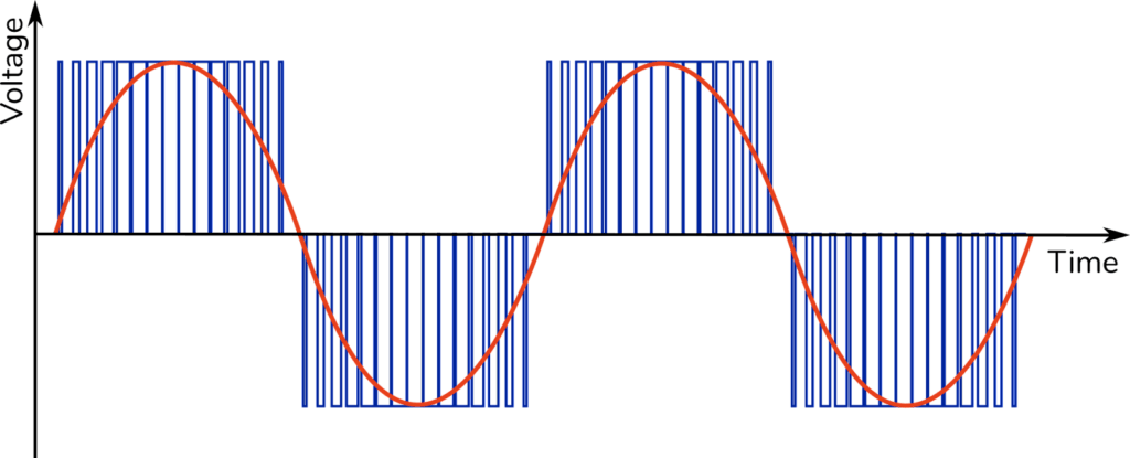
Power electronics made it possible to regulate the stator field’s frequency. The most popular method is to rectify the grid’s voltage before chopping the signal into pulses with adjustable width. It is feasible to produce a nearly sinusoidal current by carefully selecting the pulse width and taking into account the inductive nature of the stator windings. An inductive load has a frequency-dependent impedance that increases at higher frequencies. There are a lot of high frequencies on the steep flanks of a pulse-width modulation (PWM, Figure 1), but they can’t get past the stator coils. Consequently, the high-frequency voltage generates a low-frequency, nearly sinusoidal current.
The PWM signal enables the motor to run at different speeds and can also be used to control the torque. By utilizing these variable frequency drives, the speed of induction motor-driven applications can be fully controlled. There are numerous benefits, including reduced starting current, complete speed adjustment, torque control and efficient energy use. But there is also a dark side…
Variable frequency drives have a number of drawbacks, including reduced robustness, the necessity for external cooling, decreased reliability, etc., but, there are two significant drawbacks that are sometimes difficult to comprehend. The first is created by long cables and incline PWM flanks and is known as cable reflections. It mostly causes breakage and insulation damage on the motor side.
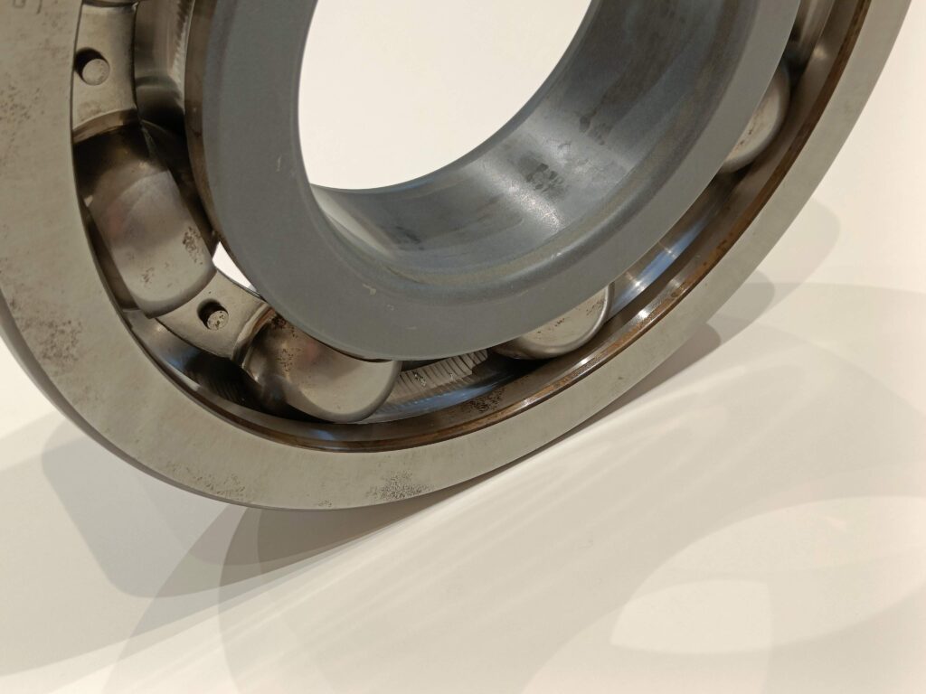
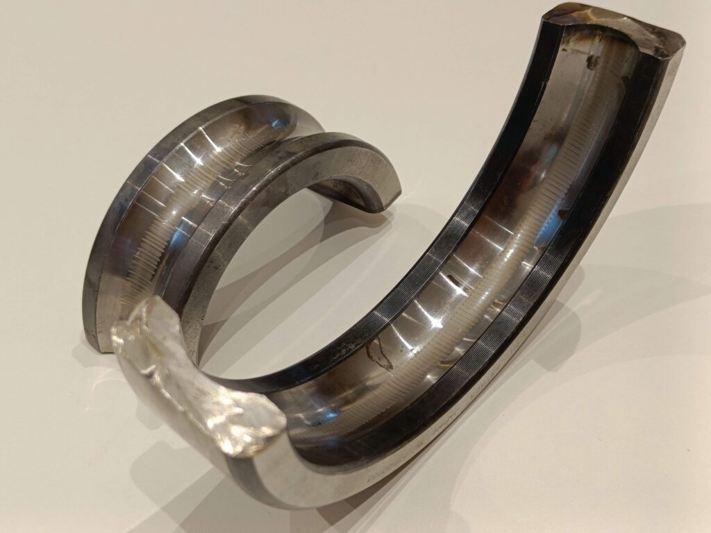
Partial discharges are another consequence. This may occur in the windings, where it will once more result in the breakdown and degradation of the insulation, or it may occur through the bearings, where it will result in bearing currents. Specific patterns on the bearings, such as the well-known washboard pattern, icing, or a yellow-brown coloration of the raceway, are produced by bearing currents (Figure 2). They eventually heat up the bearing, degrade the grease, and result in bearing failure.
As mentioned above, high frequencies are to blame for these issues. But why? In contrast to inductances, which have a high impedance at high frequencies, capacitances have a low impedance for these frequencies. Our induction motor holds lots of capacitances, which is unfortunate. A capacitance (insulation) is simply two conductors (e.g. windings) separated by a dielectric. They are known as parasitic capacitors because they are not intended to be present.
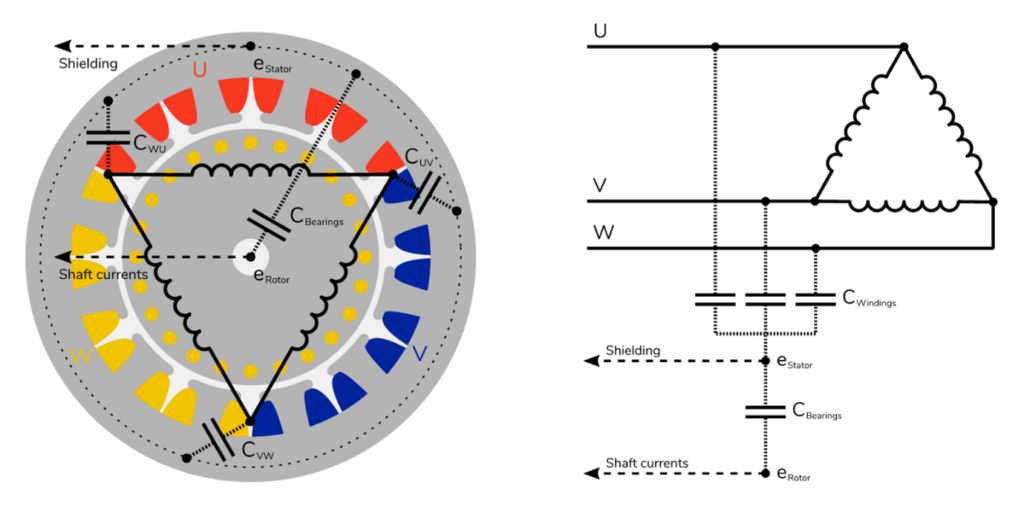
These capacitors are charged by high-frequency voltages. There are capacitors between the windings and the stator, as well as between the stator and the rotor (see Figure 3). The bearings act capacitively in this situation, more particularly, the bearing lubricate. A voltage loss occurs over the parasitic capacitances of the windings and bearings when the shielding is not connected to the stator potential. The higher the voltage’s frequency and the steeper its flanks, the higher the charging currents that can flow through the parasitic capacitances. The charging current is actually not the real problem. The troublemaker is the voltage drop across the capacitance. This voltage discharges if it exceeds the breakdown voltage. Discharges in the windings heat the insulation, hastening its deterioration. Discharges in the bearings cause the grease to degrade and the bearing to heat up and eventually fail.
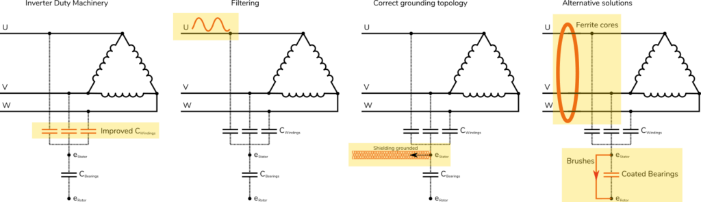
Despite the fact that it could be challenging to comprehend these issues. If you implement the proper measures in the right order, mitigating them shouldn’t be difficult. Utilising inverter duty machinery is the first step. These machines have insulation that is optimised to resist higher voltage spikes and they can operate at lower speeds without instantly overheating. It goes without saying that they are more expensive.
Reducing the high frequency in the voltage is the next stage, which can be accomplished by the use of filters. There are three different kinds of filters: dv/dt reactors, dv/dt filters and sine wave filters. The term “dv/dt” refers to the voltage to time derivative, which is a measure for the flanks’ steepness. The three different filter types will gradually provide less steep flanks, whereas sine wave filters will try to produce results that are as close to sinusoidal as possible. These filters can be used to adapt setups that have lengthy connections or no shielding (as will be mentioned below), despite the fact that they are expensive. However, the motor control cabinet needs quite a bit of room for these filters.
The next step is to make sure that the stator potential and drive potential are equal (and eventually the starpoint of the grid transformer). But this is difficult. Thick copper cables do not like to conduct high frequencies. The skin effect, which allows high-frequency currents to flow relatively close to the cable’s outer surface, is to blame for this. High-frequency currents require a low impedance channel, hence we need large surface contacts or thin woven cables like braided earthing tape. EMC glands must be used to connect to the connector box on both the motor and VFD side (Figure 4).
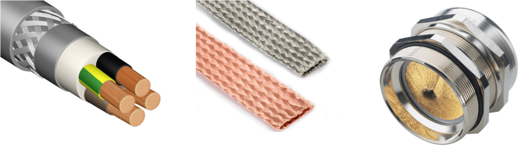
It is crucial to distinguish between grounding, which requires high surface contacts or thin woven flat wires, and earthing, or protected earth, which should transport big, low-frequency currents and is composed of thick copper cables. However, grounding should never be broken, just like with protective earth. Usually, sealings need to be bridged and paint should be removed.
Alternative remedies could only be employed if all of the aforementioned processes are impractical or fail to solve the issue. Ferrite cores, insulated bearings and ground brushes are three substitutes often used. Some of the high frequencies are filtered out by the slight lowpass filtering effect of ferrite cores. The outcome, though, is modest.
High-frequency current should not travel through an insulated bearing. These insulated layers do, however, also function as parasitic capacitances and have a breakdown voltage. Additionally, the coating of these bearings is brittle and prone to damage. By using ground brushes, you can really make a low impedance channel for the high-frequency current to travel over the bearings, saving the actual bearing. However, the issue is frequently moved, for example, to the load machine.
In conclusion, VFD-driven applications have a lot of benefits but need to be treated with care. An overview of the solutions is depicted in Figure 5. Although the effects of high-frequency voltages are not always clear, there are straightforward procedures that may be taken to alleviate the problem. Visual examination followed by measurement will frequently already reveal a lot of information. Be sure to contact a professional if you experience these issues.
By Bram Vervisch & Bram Corne, founders of Orbits Machinery Diagnostics